Modern industrial robots are true marvels of engineering. A robot the size of a person can easily carry a load over one hundred pounds and move it very quickly with a repeatability of +/-0.006 inches. Furthermore these robots can do that 24 hours a day for years on end with no failures whatsoever. Though they are reprogrammable, in many applications (particularly those in the auto industry) they are programmed once and then repeat that exact same task for years.
A six-axis robot like the yellow one below costs about $60,000. What I find interesting is that deploying the robot costs another $200,000. Thus, the cost of the robot itself is just a fraction of the cost of the total system. The tools the robot uses combined with the cost of programming the robot form the major percentage of the cost. That's why robots in the auto industry are rarely reprogrammed. If they are going to go to the expense of deploying a robot for another task, then they may as well use a new robot.

This is pretty much the typical machine people think of when they think of industrial robots. Fanuc makes this particular robot. Fanuc is the largest maker of these type of robots in the world and they are almost always yellow. This robot has six independent joints, also called six degrees of freedom. The reason for this is that arbitrarily placing a solid body in space requires six parameters; three to specify the location (x, y, z for example) and three to specify the orientation (roll, yaw, pitch for example).
If you look closely you will see two cylindrical pistons on the side of the robot. These cylinders contain "anti-gravity" springs that are a big part of the reason robots like these can carry such heavy loads. These springs counter-balance against gravity similar to the way the springs on the garage door make it much easier for a person to lift.
You will see robots like these welding, painting and handling materials.


 When teleoperation took effect, the robot's progress slowed because of all the sensory information from sensors, laser, and cameras that the humans had to deal with before assigning any particular motion to the robot. Therefore, it was important to the creators of Dante II that there be a graphical representation of all of the sensory information, in order to get an accurate picture of the terrain Dante was covering, and the state of the robot itself. By creating a graphical representation, the operators did not have to manually go through every bit of information Dante sent back from the crater and had a better chance of successfully maneuvering the robot. From this perspective, a robot like Dante II is ideal for exploration, since its sensory information is provided much more quickly and in depth than any human mapping could do. In general, this technique of displaying all the sensory information is called telepresence and has been implemented in many such applications.

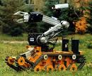
 In the early 1990s, Jet Propulsion Laboratory (JPL) in Pasadena, California began a project in Telerobotics as part of its Emergency Response Robotics Program. The primary objective of the design of HAZBOT was to allow safe exploration of potentially dangerous sites and handling of hazardous materials in conjunction with the Hazardous Materials team HAZMAT. JPL started with a commercially available REMOTEC ANDROS V robot, and added many important features to this robot with input from the JPL fire department for operation in combustible environments. For instance the special chassis and manipulator design allow all areas containing electronics and motors to be positively pressurized in the case of HAZBOT entering a combustible site. In addition, a six-degree-of-freedom manipulator with a 30 pound lift capability allows the robot to perform a variety of tasks including the unlocking and opening of doors. The manipulator also incorporates a parallel jaw gripper with a 60 pound squeeze force and a gas detector to aid in material identification. The on-board computer system, which JPL developed, controls the manipulator, track drives, and camera positioning. In addition it processes information from the temperature pressure and chemical sensors which allows the robot to provide vital information on spill location, magnitude, material type and concentration so a well prepared response team can safely enter the site. Two video cameras, one located on the gripper and the other on a movable pan/tilt platform, provide feedback to the system operator who can then control the robot from an operator control station from a distance away.

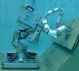
 The XM3000 Series is our third generation of Cartesian robots and yet another example of how EPSON has listened intently to customer feedback . Available in two standard sizes the XM3064 has a 600 x 400 mm XY work envelope while the XM3106 has a 1000mm x 600mm envelope. Both units come standard with the same style 150mm Z axis and +/- 360 degree tool rotation axis as the E-Series SCARA robots. And, as with the E-Series SCARA Robots, an optional 300mm Z-Axis is also available. The XM3000 is also available in a variety of other sizes and configurations such as 2 and 3 axis models


 This is pretty much the typical machine people think of when they think of industrial robots. Fanuc makes this particular robot. Fanuc is the largest maker of these type of robots in the world and they are almost always yellow. This robot has six independent joints, also called six degrees of freedom. The reason for this is that arbitrarily placing a solid body in space requires six parameters; three to specify the location (x, y, z for example) and three to specify the orientation (roll, yaw, pitch for example).


